Setting up an Arduino & DHT22 weather station
2018-03-06Ahh, Arduino. Microcontroller programming made easy accessible. There's just so much stuff you can build with it!
Sensors, home automation, robots... After all, why pay five bucks for an existing product, when you can spend
twice as much on parts and sacrifice multiple hours of your life to come up with your own, flawed solution?
In this post I'll describe my Arduino-based weather station thermometer. Let's start by listing all the required parts.
Arduino UNO
Well, duh. I used the Arduino UNO (or rather, a Chinese knock-off) mostly because that's what I had available at the time I built this monstrosity. Also, as the UNO is rather large, it's very handy for prototyping, when you're not totally sure what the end result is gonna be and want to iterate quickly.
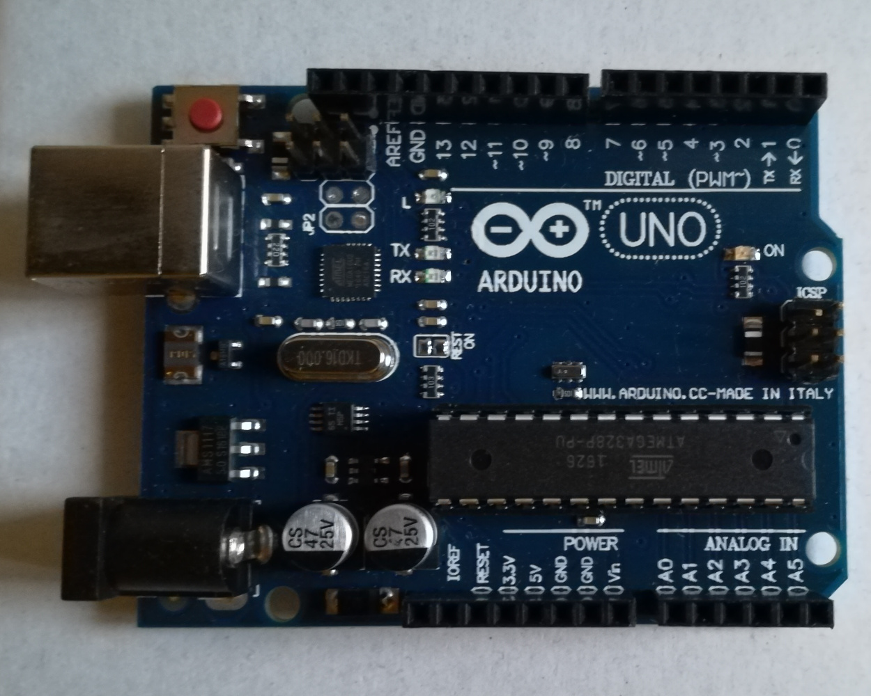
Following the old mantra of "if it ain't broke, don't fix it", I didn't bother looking into replacing the UNO with a different board later down the line.
DHT22 sensors
DHT22 is a temperature/humidity sensor commonly used in Arduino projects. It's fairly cheap and, given the price, offers quite good parameters – −40℃ to +80℃ temperature range at 0.1℃ resolution. It will happily accept any power supply between 3.3V and 6V, so it can be used in both 3.3V and 5V projects. The communication protocol is also extremely simple – if one were inclined not to use any external libraries, a quick-and-dirty version can easily be coded in some ten minutes or so.
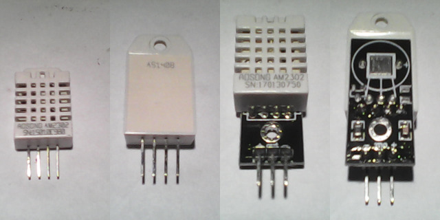
In the picture above, you can see the sensor in two versions: a "raw" one, and one with built-in pull-up resistors and thicker pins, which makes it easier to use with the Arduino. In my project, I use two sensors, since I want to measure temperature both inside and outside my flat.
An ILI9341 LCD display
ILI9341 is a common 3.3V controller chip used for powering 320×240px LCD displays. There's a myriad of no-name Chinese manufacturers producing ILI9341 displays, so finding one shouldn't be hard nor costly.
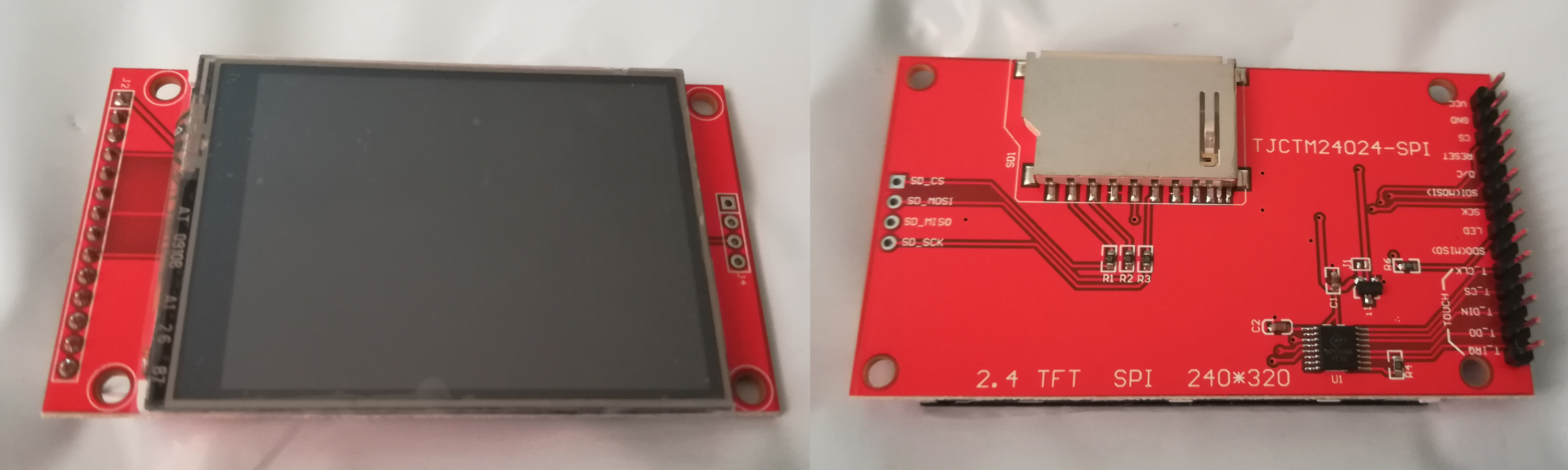
Here I've got a Chinese display that also comes with some bonus features: a touchscreen and an SD-card reader. Not that I need these extras – it's just that I was looking for the cheapest offer and well, not gonna turn it down just 'cause it's got bonus stuff. Still, the touchscreen may eventually come in handy – should I want to add some controls, I can use the screen instead of adding buttons to the project.
A logic level converter
As I was using an Arduino UNO, there was a small problem to solve: the Arduino is powered from a 5V supply, and works using 5V logic levels – whereas the display runs on 3.3V. I could go ahead and jusk hook the data cables from the Arduino directly to the display, but am I sure it can handle the voltage?
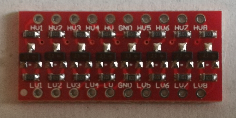
Personally, I prefer to play it safe, so I spent a few shekels on a logic level converter. Since the display works in five- or six- pin mode, a four-channel converter won't do – and six-channel ones are a bit hard to come by, so I bought an eight-channel one.
Connecting it all together
Having ordered all the parts and waited patiently for them to arrive, I could finally get around to wiring it all up. Since I'm not really doing any analog processing, the setup is rather straightforward.
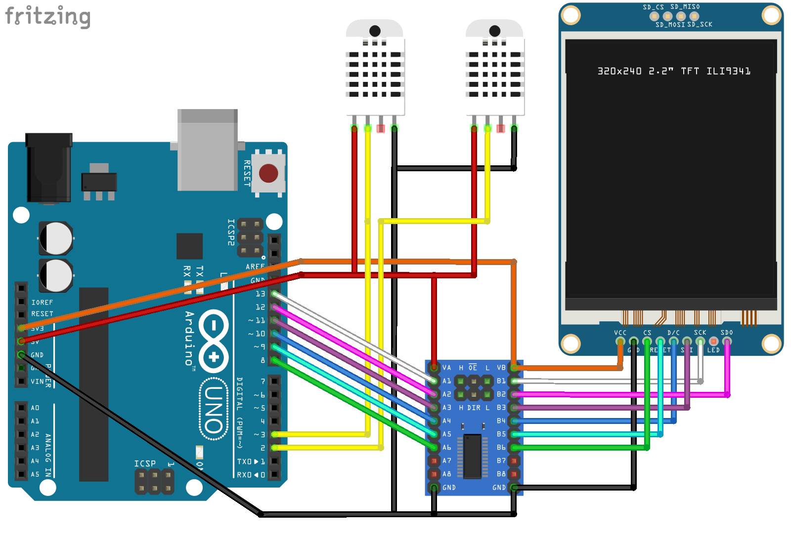
The display is connected to the Arduino through the logic-level converter. There are six pins being used on the UNO; the three hardware SPI pins: #13 (SCK), #12 (MISO), #11 (MOSI) are forced on us by the way the Adafruit ILI9341 library is written. The other three pins can be freely chosen, so I decided to go with #10 (DC), #9 (RESET) and #8 (CS) simply to keep things close together.
The temperature sensors have four pins – starting from the left, these are: VCC, data, N/C, GND. The sensors are connected directly to the Arduino, as they work fine with 5V. I used pins #2 and #3 on the UNO, mostly because I wanted to keep distance from the pins used for communicating with the display.
Designing the interface
So, after all the hardware's been connected, I could start reading data from the sensors and sending it to the display. Of course, if I wanted to just display the current temperature, I could have used a 16x2 character display. The pixel display gives much more possibilities, including displaying images and graphing. While I couldn't think of much use for images, being able to draw graphs was exactly what I had in mind when I started this project; a 24-hour graph detailing how much the temperature changed during the day would give a nice overview of the weather and allow to see whether today is hotter or colder than yesterday at about the same hour.
As mentioned before, the display is 320×240 pixels in size. Drawing the measures right next to each other could result in the graph looking a little bit jagged, so I thought it'd be good to leave a single pixel of space between the points. With two pixels per point, I'm left with a maximum of 160 measures – which isn't evently divisible by 24, though. The largest number that fits this criteria is 144; this gives a nice result of 288 pixels used for the graph, with some 32 pixels left for printing the scale and possibly some other minor info. 144 measure points mean, at 24 hour scale, 6 points per hour – or one measure per 10 minutes – which should be enough for accurately presenting the temperature changes, given the mild climate I'm living in.
While this covers the issue of width, there's also the matter of height. Reading the temperature from the graph, even with a scale, would be a bit tricky and rather imprecise – which means it's a must to display the current readings in a big font somewhere. (This has the added benefit of displaying any changes in measurements immediately, instead of having to rely on data that might be close to 10 minutes old.) The Adafruit ILI9341 library contains some functions for printing text, and the default font seems to use 5×8 characters; using a 3× scale for the current measures gives a 24px character height. Since I didn't want the graph to anyhow overlap with these big texts, I decided to limit the graph height to 210 pixels.
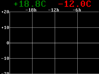
Given the assumptions above, I came up with a sketch of the UI. The graph is aligned to the bottom-right corner of the display, with the extra space on the left being used for the temperature scale, and space on the top used for the time scale and printing the current measurements in a big font. Having drawn this sketch, I realised there are two more issues that I'll need to address:
-
The temperature scale. What should the bounds be? Of course, I could pick a scale that I'd expect to be sane for the climate I live in (say, −20℃ – +40℃), but then, a lot of the time, largs parts of the graph area would be unused (e.g. the "minus" part would be rather useless in the summer). This led me to decide that the graph should auto-scale given the currently displayed temperatures; pick the lowest one and the highest one, round down/up to the nearest 10℃, and then calculate the pixels-per-10-degrees scale and use that for drawing the graph.
- The time scale. An issue very similar to the previous one: assuming a 24 hour time scale, the device would take a long time to fill up the graph and a lot of the drawing area would be unused. It would be nice if the device could start with a shorter time scale, working its way up to said 24 hours. The easiest way to do it would be to, once the graph is filled, simply squash the 144 measures to half the set size and double the time scale. I eventually decided to make the device start with a 45 minute scale, progressing through 1.5 hours, 3 hours, 6 hours and 12 hours before reaching a full day.
Writing the code
As can be expected, this was the tricky part. I started out with a version that used fixed scales, adding auto-scaling
in some later commits. The finished code latest version is a bit shy of 400 lines; while this isn't much, the code
is a bit messy and could use some improvements. But I guess that's to be expected of stuff written by one person,
to be used by themselves in a compile-and-forget fashion.
Still, if you'd like to take a look at the code yourself, I've made it available in a GitHub repository. The licence tag on this one is GNU GPLv3.
Setting it up
Having finished the code, I just needed to look for something that I could use as an improvised case for my thermometer, so I don't have to deal with wires sprawling all over the place.
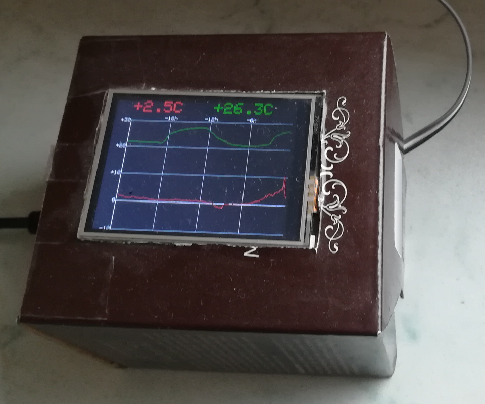
In the end, I used a leftover box for some cosmetics. It might not look the best, as it's a bit bulky; but on the other hand, it provides plenty of space, so I didn't have to worry how to fit everything inside.
Comments
Do you have some interesting thoughts to share? You can comment by sending an e-mail to blog-comments@svgames.pl.